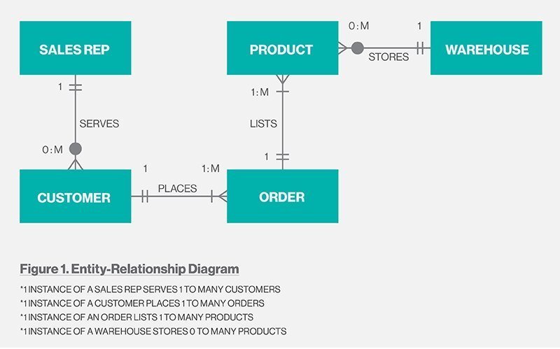
Entity Relationship Diagram (ERD) Definition
An entity relationship diagram (ERD), also known as an entity relationship model, is a graphical representation of an information system that depicts the relationships among people, objects, places, concepts or events within that system. An ERD is a data modelingechnique that can help define business processes and be used as the foundation for a relational database.
Importance of ERDs and their uses
Entity relationship diagrams provide a visual starting point for database design that can also be used to help determine information system requirements throughout an organization. After a relational database is rolled out, an ERD can still serve as a referral point, should any debugging or business process re-engineering be needed later.
However, while an ERD can be useful for organizing data that can be represented by a relational structure, it can’t sufficiently represent semi-structured or unstructured data. It’s also unlikely to be helpful on its own in integrating data into a pre-existing information system.
Main components of an ERD
ERDs are generally depicted in one or more of the following models:
- A conceptual data model, which lacks specific detail but provides an overview of the scope of the project and how data sets relate to one another.
- A logical data model, which is more detailed than a conceptual data model, illustrating specific attributes and relationships among data points. While a conceptual data model does not need to be designed before a logical data model, a physical data model is based on a logical data model.
- A physical data model, which provides the blueprint for a physical manifestation — such as a relational database — of the logical data model. One or more physical data models can be developed based on a logical data model.
There are three basic components of an entity relationship diagram:
- Entities, which are objects or concepts that can have data stored about them.
- Attributes, which are properties or characteristics of entities. An ERD attribute can be denoted as a primary key, which identifies a unique attribute, or a foreign key, which can be assigned to multiple attributes.
- The relationships between and among those entities.

For example, an ERD representing the information system for a company’s sales department might start with graphical representations of entities such as the sales representative, the customer, the customer’s address, the customer’s order, the product and the warehouse. (See diagram above.) Then lines or other symbols can be used to represent the relationship between entities, and text can be used to label the relationships.
A cardinality notation can then define the attributes of the relationship between the entities. Cardinalities can denote that an entity is optional (for example, a sales rep could have no customers or could have many) or mandatory (for example, there must be at least one product listed in an order.)
The three main cardinalities are:
- A one-to-one relationship (1:1). For example, if each customer in a database is associated with one mailing address.
- A one-to-many relationship (1:M). For example, a single customer might place an order for multiple products. The customer is associated with multiple entities, but all those entities have a single connection back to the same customer.
- A many-to-many relationship (M:N). For example, at a company where all call center agents work with multiple customers, each agent is associated with multiple customers, and multiple customers might also be associated with multiple agents.
While there are tools to help draw entity relationship diagrams, such as computer-aided software engineering (CASE) tools, some relational database management systems also have design capabilities built in.