HP Proliant Microserver Gen10 as Router or NAS

HP Proliant Microserver Gen10 as Router or NAS

HP Proliant Microserver Gen10 as Router or NAS

Introduction

In the summer of 2017, HP released the Proliant Microserver Gen10. This machine replaces the older Gen8 model.

HP Proliant Microserver Gen10 as Router or NAS

For hobbyists, the Microserver always has been an interesting device for a custom home NAS build or as a router.

Let’s find out if this is still the case.

Price

In The Netherlands, the price of the entry-level model is similar to the Gen8: around €220 including taxes.

CPU

The new AMD X3216 processor has slightly better single threaded performance as compared to the older G1610t in the Gen8. Overall, both devices seem to have similar CPU performance.

The biggest difference is the TDP: 35 Watt for the Celeron vs 15 Watt for the AMD CPU.

Memory

By default, it has 8 GB of unbuffered ECC memory, that’s 4 GB more than the old model. Only one of the two memory slots is occupied, so you can double that amount just by adding another 8 GB stick. It seems that 32 GB is the maximum.

Storage

This machine has retained the four 3.5″ drive slots. There are no drive brackets anymore. Before inserting a hard drive, you need to remove a bunch of screws from the front of the chassis and put four of them in the mounting holes of each drive. These screws then guide the drive through grooves into the drive slot. This caddy-less design works perfectly and the drive is mounted rock-solid in it’s position.

To pop a drive out, you have to press the appropriate blue lever, which latches on to one of the front screws mounted on your drive and pulls it out of the slot.

There are two on-board sata controllers.

00:11.0 SATA controller: Advanced Micro Devices, Inc. [AMD] FCH SATA Controller [AHCI mode] (rev 49)
01:00.0 SATA controller: Marvell Technology Group Ltd. 88SE9230 PCIe SATA 6Gb/s Controller (rev 11)

The Marvell controller is connected to the four drive bays. The AMD controller is probably connected to the fifth on-board SATA port.

As with the Gen8, you need a floppy-power-connector-to-sata-power-connector cable if you want to use a SATA drive with the fifth onboard SATA port.

Due to the internal SATA header or the USB2.0 header, you could decide to run the OS without redundancy and use all four drive bays for storage. As solid state drives tend to be very reliable, you may use a small SSD to keep the cost and power usage down and still retain reliability (although not the level of reliability RAID1 provides).

Networking

Just as the Gen8, the Gen10 has two Gigabit network cards. The brand and model is: Broadcom Limited NetXtreme BCM5720

As tested with iperf3 I get full 1 Gbit network performance. No problems here (tested on CentOS 7).

PCIe slots

This model has two half-height PCIe slots (1x and 8x in a 4x and 8x physical slot) which is an improvement over the single PCIe slot in the Gen8.

USB

The USB configuration is similar to the Gen8, with both USB2 and USB3 ports and one internal USB2 header on the motherboard.

Sidenote: the onboard micro SD card slot as found in the Gen8 is not present in the Gen10.

Graphics

The Gen10 has also a GPU build-in but I have not looked into it as I have no use for it.

The Gen10 differs in output options as compared to the Gen8: it supports one VGA and two displayport connections. Those displayport connectors could make the Gen10 an interesting DIY HTPC build, but I have not looked into it.

iLO

The Gen10 has no support for iLO. So no remote management, unless you have an external KVM-over-IP solution.

This is a downside, but for home users, this is probably not a big deal. My old Microserver N40L didn’t have iLO and it never bothered me.

And most of all: iLO is a small on-board mini-comuter that increases idle power consumption. So the lack of iLO support should mean better idle power consumption.

Boot

Both Legacy and UEFI boot is supported. I have not tried UEFI booting.

Booting from the 5th internal SATA header is supported and works fine (as opposed to the Gen8).

For those who care: booting is a lot quicker as opposed to the Gen8, which took ages to get through the BIOS.

Power Usage

I have updated this segment as I have used some incorrect information in the original article.

The Gen10 seems to consume 14 Watt at idle, booted into Centos 7 without any disk drives attached (removed all drives after booting). This 14 Watt figure is reported by my external power meter.

Adding a single old 7200 1 TB drive drives power usage up to 21 Watt (as expected).

With four older 7200 RPM drives the entire system uses about 43 Watt according to the external power meter.

As an experiment, I’ve put two old 60 GB 2.5″ laptop drives in the first two slots, configured as RAID1. Then I added two 1 TB 7200 RPM drives to fill up the remaining slots. This resulted in a power usage of 32 Watt.

Dimensions and exterior

Exactly the same as the Gen8, they stack perfectly.

The Gen8 had a front door protecting the drive bays connected to the chassis with two hinges. HP has been cheap on the Gen10, so when you open the door, it basically falls off, there’s no hinge. It’s not a big issue, the overall build quality of the Gen10 is excellent.

I have no objective measurements of noise levels, but the device seems almost silent to me.

Evaluation and conclusion

At first, I was a bit disappointed about the lack of iLO, but it turned out for the best. What makes the Gen10 so interesting is the idle power consumption. The lack of iLO support probably contributes to the improved idle power consumption.

The Gen8 measures between 30 and 35 Watt idle power consumption, so the Gen10 does fare much better (~18 Watt).

Firewall/Router

At this level of power consumption, the Gen10 could be a formidable router/firewall solution. The only real downside is it’s size as compared to purpose-built firewalls/routers. The two network interfaces may provide sufficient network connectivity but if you need more ports and using VLANs is not enough, it’s easy to add some extra ports.

If an ancient N40L with a piss-poor Atom processor can handle a 500 Mbit internet connection, this device will have no problems with it, I’d presume. Once I’ve taken this device into production as a replacement for my existing router/firewall, I will share my experience.

Storage / NAS

The Gen8 and Gen10 both have four SATA drive bays and a fifth internal SATA header. From this perspective, nothing has changed. The reduced idle power consumption could make the Gen10 an even more attractive option for a DIY home grown NAS.

All things considered I think the Gen10 is a great device and I have not really encountered any downsides. If you have no problems putting a bit of effort into a DIY solution, the Gen10 is a great platform for a NAS or Router/Firewall, that can compete with most purpose-build devices.

HP C7000 Enclosure fan location rules

HP C7000 Enclosure fan location rules

HP C7000 Enclosure fan location rules

The HP BladeSystem c7000 Enclosure ships with four HP Active Cool fans and supports up to 10 fans. You must install fans in even-numbered groups, based on the total number of server blades installed in the enclosure, and install fan blanks in unused fan bays.

Four Fan Rule

HP BladeSystem 67145 c7000 Enclosure fan location rules

Fan bays 4, 5, 9, and 10 are used to support a maximum of two devices located in device bays 1, 2, 9, or 10. Note that only two of the device bays can be used with four fans.

Six Fan Rule

HP BladeSystem 67146 c7000 Enclosure fan location rules

Fan bays 3, 4, 5, 8, 9, and 10 are used to support a maximum of eight devices in device bays 1, 2, 3, 4, 9, 10, 11, or 12.

Eight Fan Rule

HP BladeSystem 67148 c7000 Enclosure fan location rules

Fan bays 1, 2, 4, 5, 6, 7, 9, and 10 are used to support a maximum of 16 devices in the device bays.

Ten Fan Rule

HP BladeSystem 67149 c7000 Enclosure fan location rules

All fan bays are used to support a maximum of 16 devices in the device bays.

Adjusting UEFI boot order on ProLiant DL580 Gen8

Adjusting UEFI boot order on ProLiant DL580 Gen8

Adjusting UEFI boot order on ProLiant DL580 Gen8

When HP introduced the ProLiant DL580 Gen8 last February, HP also launched it’s new UEFI firmware, which replaced traditional BIOS and became the standard across all ProLiant Gen9 servers introduced last September.  Typically, the powerhouse ProLiant DL580 servers lag behind the introduction of other generational servers and the Gen8 model was no different, being introduced well over a year after Gen8 debuted.  Its pretty safe to assume that HP sells many less units of the DL580 model than other ProLiant rackmounts and it was a pretty smart strategic move to add UEFI to this model before launching it across the entire line of mass-market servers.

Some of the menus in the UEFI inteface on the ProLiant DL580 Gen8 are a little clunky.  One of those is the boot order screen.  After several failed attempts at changing the boot order, I engaged the help of a product manager within HP who explained where I was going wrong.  And for the benefit of others, I wanted to put this out to explain how to make boot order changes on the ProLiant DL580 Gen8.  The trickiness comes when you actually make the change – getting to the boot options is straight forward.

Fortunately, the same product manager confirmed that ProLiant Gen9 servers have an improved version with clearer instructions.

Changing Boot Order on a DL580 Gen8 with UEFI

During the normal boot sequence, you get the normal POST screens and options along the bottom – one of those is F9 for System Utilities and you should press F9 to invoke those menus.

FmenuOptions

Once the System Utilities menu appears, choose the System Configuration option and press enter.

systemConfig

From System Configuration, you will choose Boot Options and press enter.

bootOptions

From the Boot Options, you come to the RBSU and the first option is the UEFI Boot Order.  Choose UEFI Boot Order and press enter.

This screen also confirms whether you are using UEFI Mode or Legacy BIOS for booting.  If you wanted to make a change, this is the screen where you change to Legacy BIOS from UEFI or vice versus.  If you make a boot mode change, all options will get greyed out and you will need to reboot and go back into System Utilities to make further changes.  

rbsuMenu

Once you’re in the UEFI Boot Order screen, you see a list of options along with brief instructions.

bootOrderScreen

You must press enter to go into the boot order screen and make changes.  Scroll to the item you want to move in boot order and press the + or – keys to move the item up or down the list.

makeChanges

Once you make the changes, press Enter to save those changes.  There is no onscreen prompt that says this, but pressing F10, even though it says Save in the display, will not save it.  Pressing ESC will lose your changes.

savedChanges

Once you press Enter, you go back to a screen and should see your new boot order confirmed.  You may press F10 here to save the settings.  Press Enter as instructed on the on-screen prompt and this saves the changes.

pressF10

When the system reboots, now you should immediately begin booting from your USB device or hard drive that you moved to the first position in boot order.

How to configure a small redundant iSCSI infrastructure for VMware

How to configure a small redundant iSCSI infrastructure for VMware

How to configure a small redundant iSCSI infrastructure for VMware

I’ve seen often many users asking in forums how to properly configure a network in order to deploy a iSCSI storage, especially in really small environments.

So, I created this post in order to explain how I usually configure a system with an HP StorageWorks P2000 G3 iSCSI storage and a small cluster with 3 vSphere servers. If you are using a different storage, you would probably have to change some configuration, but the principles are always the same.

Needed Hardware

3 VMware vSphere 5.x servers (usually with a Essentials Plus VMware license) . In these situations, I usually dedicate two network cards to iSCSI. That’s because many modern servers have already 4 NICs onboard, so I have two dedicated connections for iSCSI and the other two for all other connection types, like management, vmotion and virtual machines, without having to buy additional network cards.

DL360e gen8 Rear

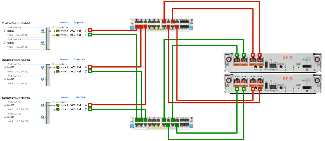
2 Gigabit ethernet switches with at leat 7 ports each. If you need to add the iSCSI network to an existing infrastructure and youwant to keep it super simple, avoid VLANs and have total physical separation, you would need at leat 14 network ports. This is also useful if your low-end switches have problems in managing VLANS or you are not an expert with them; iSCSI network will be separated, and not connected to anything else. You will connect 8 ports from storage array and 2 from each server. Total is 14, distributed on two switches for redundancy. If instead the switches are going to manage iSCSI and other networks at the same time (by using VLANs), then you will need more ports, in order to manage all vSphere networks, and uplinks to other parts of the network.

1 storage HP P2000 iSCSI, with two storage processors having 4 iSCSI connections each, as in this picture:

Rear of a HP P2000 iSCSI

Network configuration

The goal of a iSCSI storage network, as in any storage fabric, is to offer redundant connections from sources to destination (ESXi servers and the P2000 in this scenario), so that none of the possible failures in any elements of the chain can stop the communication between source and destination. This goal can be reached by having two completely separated networks, each managed by a different switch.

iscsi-vsphere

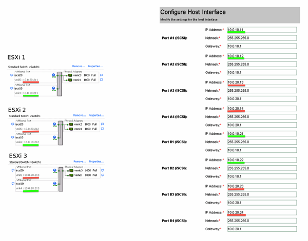
A completely redundant iSCSI network has several IP addresses; that’s because each path is made by any source-destination IP combination. In order to simplify the configuration of all the IP addresses, I usually follow this scheme:

P2000 ESXi iSCSI IP addressing

All IP addresses of Network 1, marked in green, are using a base address like 10.0.10.xxx, and the 10 of the third octect means the Network 1. By the same scheme, Network 2 has a base address 10.0.20.xxx. Also, all the ESXi port groups are following this numbering scheme. In this way it’s easy to assign addresses and be sure each component lays in the correct network with the right IP address.

vSphere configuration

Inside any ESXi server, you first of all need to enalbe the software iSCSI initiator; then you create two vmkernel ports and bind them to only one of the two network cards, one per vmkernel port:

iSCSI binding

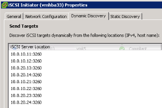
Then you input into the Dynamic Discovery all the IP addresses of the iSCSI storage:

iSCSI initiator

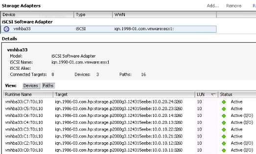
After a rescan, you configure the Path Selection Policy of all datastores to be Round Robin, and the final result is going to be like this:

Multipaths

HP c7000 Blade Enclosure Configuration

HP c7000 Blade Enclosure Configuration


Managing you blade infrastructure might be sometimes challenging. I decided to guide you through components of HP c7000 Enclosure and components you can use. After short introduction I went through initial configuration and additional settings which I thing are quite useful.

HP c7000 Enclosure overview

The HP BladeSystem c7000 Enclosure goes beyond just Blade servers. It consolidates server, storage, networking and power management into a single solution that can be managed as a unified environment.

The BladeSystem c7000 enclosure provides all the power, cooling, and I/O infrastructure needed to support modular server, interconnect, and storage components today and throughout the next several years. The enclosure is 10U high and holds up to 16 server and/or storage blades plus optional redundant network and storage interconnect modules.

Intelligent Infrastructure support: Power Discovery Services allows BladeSystem enclosures to communicate information to HP Intelligent PDUs that automatically track enclosure power connections to the specific iPDU outlet to help ensure redundancy and prevent downtime. Location Discovery Services allows the c7000 to automatically record its exact location in HP Intelligent Series Racks, eliminating time-consuming manual asset tracking.

HP BladeSystem Onboard Administrator is the built-in enclosure management processor, subsystem, and firmware base used to support the HP BladeSystem c-Class enclosures and all the managed devices contained within them. Onboard Administrator provides a single point from which to perform management tasks on server blades or switches within the enclosure.
Together with the enclosure’s HP Insight Display, the Onboard Administrator was designed for both local and remote HP BladeSystem c-Class administration.

This module and its firmware provide:
• Wizards for simple, fast setup and configuration
• Highly available and secure local or remote access to the HP BladeSystem infrastructure
• Security roles for server, network, and storage administrators
• Automated power and cooling of the enclosure
• Agentless device health and status
• Power and cooling information and control

Each enclosure ships with an Onboard Administrator module/firmware. HP BladeSystem Platinum Enclosures can be configured with redundant Onboard Administrator modules to provide uninterrupted manage ability of the entire enclosure and blades. When two Onboard Administrator modules are present, they work in an active-standby mode, assuring full redundancy of the enclosure’s integrated management.

HP c7000 Enclosure specification

Technical features

System fan features

  • 10 Active Cool 200 Fans

Form factor

  • 8 Full Height Blades/16 Half-Height Blades
  • Mixed configurations supported

BladeSystems supported

  • HP ProLiant, Integrity and Storage blades in either mixed or homogenous configurations

Management features

  • OneView (OV) software License

Power availability

  • 2400W (6) 1 phase Platinum power supply kits

What’s included

  • (1) HP BLc7000, (6) Power Supplies, (10) Fans, (1) Onboard Administrator with KVM, and, (16) ROHS Full Licenses OneView

Product differentiator

  • 1 Phase 6 Pwr Supplies 10 Fans ROHS 16 OV Lic

Warranty

  • 3/3/3 (parts-labor-onsite)

Dimensions and weight

Dimensions (W x D x H)

  • 75.89 x 60.65 x 101.29 cm (29.88 x 23.88 x 39.88 in)

Weight

  • 136.08 kg (300 lb)

HP c7000 Enclosure interconnects

HP Virtual Connect

HP Virtual Connect is an essential building block for any virtualized or cloud-ready environment. This innovative, wire-once HP connection management simplifies server connectivity, making it possible to add, move, and change servers in minutes vs. hours or days. Virtual Connect is the simplest way to connect servers to any network and reduces network sprawl at the edge by up to 95 percent.

Main two types Virtual Connect modules used by customers are HP Virtual Connect FlexFabric and HP Virtual Connect Flex-10.

HP Virtual Connect FlexFabric


In short word first one act as pass-thru device and is compatible with all other NPIV standards-based switch products. Any changes to the server are transparent to its associated network, cleanly separating the servers from SAN and relieving SAN Administrators from server maintenance.

QuickSpecs

Performance

  • (8) 2/4/8Gb Auto-negotiating Fibre Channel uplinks connected to external SAN switches
  • (2) Fibre Channel SFP+ Transceivers included with the Virtual Connect Fibre Channel Module
  • (16) 1/2/4/8Gb Auto-negotiating Fibre Channel downlink ports provide maximum HBA performance
  • HBA Aggregation on uplinks ports using ANSI T11 standards-based N_Port ID Virtualization (NPIV) technology
  • Allows up to 255 virtual machines running on the same physical server to access separate storage resources
  • Extremely low latency throughput provides switch-like performance.

Management

  • Storage management is no longer constrained to a single physical HBA on a server blade
  • Managed with the Virtual Connect Ethernet Module
  • Does not add to SAN switch domains or require traditional SAN management
  • Appears as a pass-thru device to the SAN Manager

Virtual server profiles

  • Provisioned storage resource is associated directly to a specific virtual machine – even if the virtual server is re-allocated within the BladeSystem
  • Ability to pre-configure server I/O connections
  • Ability to move, add, or change servers on the fly
  • Once defined, SAN Administrators don’t have to be involved in server changes

HP Virtual Connect Flex-10/10D


Performance

  • 16 x 10Gb downlinks to server NICs
  • Each 10Gb downlink supports up to 4 FlexNICs or 3 FlexNICs and 1 iSCSI FlexHBA
  • Each iSCSI FlexHBA can be configured to transport Accelerated iSCSI protocol.
  • Each FlexNIC and iSCSI FlexHBA is recognized by the server as a PCI-e physical function device with adjustable speeds from 100Mb to 10Gb in 100Mb increments when connected to a HP NC553i 10Gb 2-port FlexFabric Converged Network Adapter or any Flex-10 NIC and from 1Gb to 10Gb in 100Mb increments when connected to a NC551i Dual Port FlexFabric 10Gb Converged Network Adapter or NC551m Dual Port FlexFabric 10Gb Converged Network Adapter including NC554FLB Dual Port FlexFabric Adapter
  • 4 x 10Gb cross connects for redundancy and stacking
  • 10 x 10Gb SR, LR, or LRM fiber and copper SFP+ uplinks
  • Supports up to 4 FlexNICs per 10Gb server connections.
  • Each FlexNIC is recognized by the server as a PCI-e physical function device with customizable speeds from 100Mb to 10Gb.
  • Line Rate, full-duplex 600 Gbps bridging fabric
  • 1.0 μs latency
  • MTU up to 9216 Bytes – Jumbo Frames
  • Supports up to 128K MAC addresses and 1K IGMP groups
  • VLAN Tagging, Pass-Thru and Link Aggregation supported on all uplinks
  • In tunneled VLAN mode, up to 4,096 networks are supported per network uplink and server downlink. In mapped VLAN mode, up to 1,000 networks are supported on network uplinks per Share Uplink Set, domain or module and on server downlinks up to 162 networks are supported per 10Gb physical port (VC v3.30 or later).
  • Stack multiple Virtual Connect Flex-10/10D modules with other VC Flex-10/10D, VC FlexFabric or VC Flex-10 across up to 4 BladeSystem enclosures allowing any server Ethernet port to connect to any Ethernet uplink

Management

  • Virtual Connect Manager is included with every module
  • HTTPS and a secure, scriptable CLI interface is ready out of the box. Easy setup and management via the Onboard Administrator interface
  • SNMP v.1, v.2 and v.3, provide ease of administration and maintenance.
  • Port Mirroring on any uplink provides network troubleshooting support with Network Analyzers
  • IGMP Snooping optimizes network traffic and reduces bandwidth for multicast applications such as streaming applications
  • Role-based security for network and server administration with LDAP, TACACS+ and RADIUS compatibility
  • Remotely update Virtual Connect firmware on multiple modules using Virtual Connect Support Utility 1.10.1 or greater
  • CLI auto-filling with TAB key
  • GUI and CLI session timeout for security
  • QoS configurable based on DOT1P and DSCP
  • Configurable filtering of multicast traffic
  • sFlow monitoring

Virtual Connect Server Profiles

  • Create up to 4 individual FlexNICs with their own dedicated, customized bandwidth per 10Gb downlink connection.
  • Set FlexNIC speeds from 100Mb to 10Gb per connection
  • Allows setup of server connectivity prior to server installation for easy deployment
  • Ability to move, add, or change server network connections on the fly
  • Once defined, LAN and SAN administrators don’t have to be involved in server changes

Fibre Channel Switches

Brocade 8Gb SAN Switch


Advanced Fabric Services

  • Hardware Enforced Zoning (included)
  • Dynamic Path Selection (included)
  • WebTools (included)
  • Enhanced Group Management (EGM)
  • Power Pack+ fabric services software bundle (optional)
    • Fabric Vision
    • ISL Trunking
    • Fabric Watch
    • Extended Fabrics
    • Advanced Performance Monitoring
  • Secure Fabric OS (included in base FOS)
  • SAN Network Advisor (optional)

Manageability

  • WebTools (included)
  • Enhanced Group Management (EGM)
  • Advanced Performance Monitoring (optional Power Pack+ upgrade)
  • HP OnBoard Administrator (included with HP BladeSystem)
  • HP Systems Insight Manager (included with HP BladeSystem)
  • HP Storage Essentials (optional)
  • API
  • SNMP

Interoperability

Brocade Access Gateway enables Brocade embedded SAN switches to interoperate with other SAN fabrics running supported firmware. While in Brocade Access Gateway mode, the device must also be connected to an NPIV-enabled edge switch or director. Supported edge environments are listed in the Brocade Fabric OS® release notes.

HP c7000 Enclosure configuration

HP c7000 Enclosure configuration – Insight Display

First step to configure enclosure is IP address configuration using Insight Display.

  1. Navigate to Enclosure Settings

  2. Navigate to Active OA and click OK.
  3. Navigate to Active IPv4 and click OK.
  4. Choose proper value – static IP configuration or DHCP and click OK.
  5. Interface will direct you to Accept button. Click OK.
  6. Now you can enter your IP address. It takes a while and after setting IP address go to Accept.
    HP c7000 Enclosure configuration - Insight Display 6
  7. Do the same with second Onboard Administrator module and now we can switch to web based configuration.

HP c7000 Enclosure configuration – First Time Setup Wizard

After you successfully login to enclosure you will be welcome by First Time Setup Wizard. We will go through it since it configure majority of settings.

    1. Check Do not automatically show this wizard again if you don’t want to be bothered again by this wizard. Click Next.
      HP c7000 Enclosure configuration - First Time Setup Wizard 1
    2. On the next screen you can choose to enable FIPS (Federal Information Processing Standards) which is in simple words set of standard cryptographic modules. Select it according to your needs.
    3. Select your enclosure and click Next.
    4. If you have previously saved configuration file you can use it to set up enclosure.
    5. Configure Rack Name, Enclosure Name and Date and Time. I suggest to use NTP server to have always up to date time and date settings.
    6. You can change password for Administrator and enable PIN protection before using the enclosure’s Insight Display. Click Next.
    7. In next section we can create additional Local User Accounts. Let us create one just to show you how do we do it. Click New.
      HP c7000 Enclosure configuration - First Time Setup Wizard 7
    8. Provide User Name, password and Privilege Level. On the right part of the screen choose where user should have access. At the end click Add User.
    9. On the next screen we will configure EBIPA – Enclosure Bay IP Addressing. EBIPA is internal DHCP scope for Blades iLO and devices in enclosure bays (HP Virtual Connect or HP Access Gateway). Click Next.
      HP c7000 Enclosure configuration - First Time Setup Wizard 9
    10. We need to fill in First EBIPA Address, Subnet Mask, Gateway, Domain and DNS Servers. Next step is to click button Autofill which will fill in whole range.
      HP c7000 Enclosure configuration - First Time Setup Wizard 10
    11. We do the same for Interconnect Bays and click Next.
      HP c7000 Enclosure configuration - First Time Setup Wizard 11
    12. You can configure IPv6 in the same way. I skipped this and I moved ahead to next step.
    13. Next step is to configure Directory Groups.
      HP c7000 Enclosure configuration - First Time Setup Wizard 12
    14. Click New and add Group Name, set privilege level and gave group necessary permissions. After that click Add Group.
      HP c7000 Enclosure configuration - First Time Setup Wizard 13
    15. Click Next and we will setup Directory Settings.
    16. Select Enable LDAP Authentication and Use NT Account Name Mapping (DOMAIN\username).
      Provide following settings:

      1. Directory Server Address.
      2. Directory Server SSL Port.
      3. Search Context.
        HP c7000 Enclosure configuration - First Time Setup Wizard 14
    17. Click Next and we will go ahead to Network Settings.
      HP c7000 Enclosure configuration - First Time Setup Wizard 15
    18. Provide settings for both Onboard Administrator modules.
        1. DNS Host Name
        2. IP Address
        3. Subnet Mask
        4. Gateway
        5. DNS Server 1
        6. DNS Server 2

      HP c7000 Enclosure configuration - First Time Setup Wizard 16

    19. Click Next ( I skipped IPv6 configuration) and we will go ahead with next wizard setting.
    20. Almost at the end you can configure SNMP Settings. In my wizard I skipped it.
      HP c7000 Enclosure configuration - First Time Setup Wizard 17
    21. Last step is to set Power Management settings.
      1. Power Mode – select AC Redundant, Power Supply Redundant or Not Redundant.
        1. AC Redundant – In this configuration N power supplies are used to provide power and N are used to provide redundancy.
        2. Power Supply Redundant: Up to 6 power supplies can be installed with one power supply always reserved to provide redundancy.
        3. Not Redundant: No power redundancy rules are enforced and power redundancy warnings will not be given.
          HP c7000 Enclosure configuration - First Time Setup Wizard 18
      2. Dynamic Power – This mode is off by default since the high-efficiency power supplies save power in the majority of situations. When enabled, Dynamic Power attempts to save power by running the required power supplies at a higher rate of utilization and putting unneeded power supplies in standby mode.
        HP c7000 Enclosure configuration - First Time Setup Wizard 19
      3. Power Limit – Power Limit AC Input Watts over this set limit.
        HP c7000 Enclosure configuration - First Time Setup Wizard 20
    22. Click Next and you will finish First Time Setup Wizard.
      HP c7000 Enclosure configuration - First Time Setup Wizard 21

HP c7000 Enclosure configuration – Additional Settings

HP c7000 Enclosure additional settings – Directory Settings

In order to use Active Directory authentication we need to import domain controller certificate into enclosure.

  1. Go to Users/Authentication expand Local Users and click to Directory Settings.
    HP c7000 Enclosure configuration - Additional Settings 1
  2. Click on Certificate Upload, paste your certificate and click Upload.
    HP c7000 Enclosure configuration - Additional Settings 2
  3. Last step is to test settings. Navigate to Test Settings tab. In order to do it give username and password and click test settings.
    HP c7000 Enclosure configuration - Additional Settings 3
  4. After you click Test Settings you have to wait a while for test result.
    HP c7000 Enclosure configuration - Additional Settings 4
  5. If everything is set up correctly you should see success. In my case I don’t have Passed in all cases because I can’t ping domain controller, but authentication works.
    HP c7000 Enclosure configuration - Additional Settings 5

HP c7000 Enclosure additional settings – Enclosure IP Mode

Similar to Virtual Connect Module, Onboard Administrator support “virtual IP mode”. In simple words it means that by accessing OA you will be always redirected to active OA in enclosure. In order to enable it go to Enclosure Settings click Enclosure TCP/IP Settingsand you will find setting in IPv4 Settings tab. Select Enclosure IP Mode and click Apply.

HP c7000 Enclosure configuration - Additional Settings 6


HP c7000 Enclosure additional settings – Onboard Administrator Active/Standby Transition

Another quite useful feature in Onboard Administrator is possibility to switch between Active and Standby OA. In order to switch you simply need to click Transition Active to Standby in Enclosure Settings, Active to Standby.

HP c7000 Enclosure configuration - Additional Settings 7


HP c7000 Enclosure additional settings – Link Loss Failover

Link Loss Failover allows monitoring of network link status of the Active Module. If we enable this function in case Active OA loose network automatic failover to Standby OA will happen. To enable it navigate to Enclosure Settings and click Link Loss Failover. Select Enable Link Loss Failover, provide Failover Interval in seconds and lick Apply.

HP c7000 Enclosure configuration - Additional Settings 8

Summary

This concludes HP c7000 Enclosure configuration. I hope you will find it useful and you enjoyed it.

8759 total views, 20 views today

wojcieh
Social Media

Wojcieh

Consultant at VMware Global, Inc.

I am innovative and experienced VMware and Windows Server Engineer with over 10 years in the IT industry specializing in VMware virtualization and Microsoft Server environment.

My experience and skills has been proven by leading vendor certifications like VMware Certified Advanced Professional 5 – Data Center Administration, VMware Certified Advanced Professional 5 – Data Center Design, Microsoft MCITP Server Administrator, ITIL V3, VMware vExpert 2014 – 2016 Award.


HP announces OneView integration with vCenter Server

HP announces OneView integration with vCenter Server

HP announces OneView integration with vCenter Server

oneviewheader

Today at VMware Partner Exchange (PEX), HP announced vCenter Server integration for its HP OneView systems management package.  Using REST API calls to HP OneView, the vCenter plugin is now able to initiate actions in HP OneView directly from the vSphere Web Client.  HP OneView, introduced last September, is a central platform of the Converged Systems group and it is the glue that takes disparate components and makes them into a cohesive solution.  The current version has support for HP BladeSystem, Virtual Connect and Gen8 ProLiant blades and rack-mount systems.  Proliant G7 blades are also supported.  It has a roadmap for adding support with HP networking and HP storage in the future.  HP OneView provides both deployment, management and monitoring capabilities so that administrators can build out solutions and maintain solutions.

HP Grow Cluster - vCenter with OneView

HP Grow Cluster Dialog

As part of a demo of the integration, HP is showing off the ability to completely automate the build and deployment of ESXi nodes in a new cluster and into existing clusters.  By utilizing OneView’s engine, a VMware administrator can kick off the orchestration of a new hardware build directly from vSphere Web Client using a simple “HP Grow Cluster” menu item (pictured above).  The menu item kicks off a wizard drive workflow (at right) that calls the tasks in OneView via its REST API.  The vCenter plugin allows the administrator to pick a reference server profile, create multiple server profiles from the template and then uses HP Server Provisioning to deploy an ESXi host build plan.

At the core of OneView is the software-defined model of IT – where the underlying hardware is abstracted from the software-based configuration and settings.  The reference server profiles define a base level of hardware and combined with settings, including firmware levels, BIOS settings and the ProLiant server model and generation preferences.   Once the reference profile is deployed, it becomes a server profile assigned to physical hardware.  Like Virtual Connect server profiles, these are portable and can be migrated between physical hardware.

31201iAB4385AD6CD0A261Customers who are familiar with HP’s Insight Control for vCenter will notice many similarities between the OneView integration and the Insight Control integration.  The OneView plugin for vCenter shows network diagrams of port mappings and configuration as well as end-to-end storage mapping from the VM to the LUN and storage array.  The current iteration of OneView relies on the same Insight Control for vCenter storage plugin.  OneView has yet to adopt storage control and management directly into its platform, though it seems safe to expect its coming given HP’s direction.

The majority of this announcement is that VMware administrators can now kick off OneView tasks directly from the vSphere Web Client, monitor and view the progress and completion of the tasks it spawns.  OneView is still in early in its life, but the interface is simple and intuitive.  Its not overly complex at this time and its build with modern concepts, like search, deeply integrated into the core product.  Extensions like the vCenter plugin are great enhancements for administrators who are accustomed to working in a native platform and gain access to the capabilities of OneView directly from a familiar console.  This release continues on HP’s track record of delivering usable functionality directly to VMware administrators from vCenter.

The HP team has a video demonstration of the HP Grow Cluster feature in the vCenter Web Client posted at hp.com.  It is definitely worth a watch to see the entire process orchestrated with just a few clicks and settings.

Mid-plane is replaced on our blade enclosure

Mid-plane is replaced on our blade enclosure

Mid-plane is replaced on our blade enclosure

Last night, we undertook replacing our mid-plane in the blade enclosure that had problems last month.  It was the first recommendation from HP support after several hours of working with various teams, but both our internal team and our HP field service guys didn’t feel it was the cause.  Turns out, we may have been very wrong with our initial hesistance, but I’m getting ahead of myself.

After a month of continued support and working the case, we escalated the case to a level where an engineer reviewed all the steps, troubleshooting, and case information to ensure nothing had been missed and to help diagnose the issue.  He came back to the original conclusion – that after all else was eliminated, the mid-plane must be the culprit.  So, we scheduled the replacement.

The actual hardware replacement went smoothly and took less than an hour to complete.  The midplane is a lot more bulky the I expected when I first saw it.  It is a single piece of hardware with interconnects on both sides that connect blades to interconnect bays, power sources to power consumers and LCD display to the logic.  But, I guess I was surprised that it was a good 2 to 3 inches thick.  In my mind, I expected a single piece of copper sitting in the middle – yes I realize now that’s stupid.

Something interesting occurred after replacing the mid-plane.  Apparently, Virtual Connect did not see the system serial number that it expected and so it reverted to its default configuration.  So, word of advice to anyone replacing a mid-plane.  Leave your VC modules ejected so that you don’t lose your domain configuration.  From talking with support, Virtual Connect needs constant communication with the OA to function (another dependancy we were not aware of).  The serial number stored reported by the OA from the enclosure is also very important to VC.  Its part of the configuration file for VC.  It all makes logical sense, but it was not spelled out in the support document detailing the mid-plane replacement.

After unsuccessfully attempting to restore my backup for the Virtual Connect domain, I opted to build it from scratch by hand.  It took about an hour and half to do for my 5 blades, but I feel better about it.  I am still worried about not being able to restore my VC domain configuration, but I attribute that problem to the hardware replacement.

Path failures on ESX4 with HP storage

Path failures on ESX4 with HP storage

Path failures on ESX4 with HP storage

Since we began upgrading our clusters to ESX4, we have been having strange “failed physical path” messages in our vmkernel logs.  I don’t normally post unless I know the solution to a problem, but in this case, I’ll make an exception.  Our deployment has been delayed and plauged by the storage issues that I mentioned in an earlier post.  Even though we have fixed our major problems, the following type errors have persisted.

Our errors look like this:

vmkernel: 19:18:05:07.991 cpu6:4284)NMP: nmp_CompleteCommandForPath: Command 0x2a (0x410005101140) to NMP device “naa.6001438005de88b70000a00002250000” failed on physical path “vmhba0:C0:T0:L12” H:0x2 D:0x0 P:0x0 Possible sense data: 0x0 0x0 0x0.
vmkernel: 19:18:05:07.991 cpu6:4284)WARNING: NMP: nmp_DeviceRequestFastDeviceProbe: NMP device “naa.6001438005de88b70000a00002250000” state in doubt; requested fast path state update…

After several cases with VMware and HP technical support, we are no closer to resolving the issues.  VMware support, for its part, has done a good job of telling us what ESX is reacting to and seeing.  HP support, on the other hand, has been circling around the problem but has made little progress in diagnosing the issue.  We have had an ongoing case for several months and our primary EVA resource at HP has continually examined the EVAperf information and SSSU output that we have sent to HP for analysis.  Those have turned up nothing, and yet the messages continue from VMware.

The errors in the log make sense to me – we are losing a path to a data disk (sometimes even a boot-from-SAN ESX OS disk!) – but why HP cannot see anything in our Brocade switches or within the EVA is beyond me.   Our ESX hosts, whether blade or rack-mounted hardware, are seeing the problems across the board.  The one cluster we waited to upgrade never saw the issues in ESX3.5, but sees them now in ESX4.  And perhaps it is a VMware issue that is just too sensitive in monitoring its storage, but I suspect its something else.   The messages don’t seem to affect operation on the hosts, but it certainly makes investigating problems difficult when trying to determine what is a real problem versus just another failed path message.  Anyone else seeing this?

HP adds firmware release sets for Bladesystem

HP adds firmware release sets for Bladesystem

HP adds firmware release sets for Bladesystem

HP has updated their framework for BladeSystem firmware and driver releases through a consolidated Service Pack for Proliant.  See this post for more information.

HP added the idea of release sets for Bladesystem firmware starting in January.  On a conference call yesterday, we were alerted to the new release set certification process.  Previously, HP had been releasing firmware for the Bladesystem as components and firmware were updated, which they still do, but the idea of a release set adds an additional cross-testing process to ensure that firmware from each component works together correctly.  There was no publicly disclosed certification process prior to January.

To quote the HP engineer on the call — there were just too many combinations and possibilities to be able to certify all available firmwares — and so the idea of a release set began in January.  The release sets are available in a compatibility matrix on the HP Bladesystem page (http://h18004.www1.hp.com/products/blades/components/c-class.html) — look at the Compatibility tab.

The good news is that in our environment, we are close to compliance with the January release set.  The only thing out of compliance for the January release is our blade ROM, PMC and iLO firmware, but, as we were also informed, this is not a good situation to be in.

Something I already knew is that we have a bottom-up firmware topology for the HP Bladesystem — meaning that we have to update the bottom level components first and then move up.  I knew this applied to the interconnects and onboard administrator modules, but it also extends to blade servers also.   In addition, the blade servers are at the lowest level and should be updated first — particularly the iLO.

The reason for this is that new OA and interconnect firmware may introduce features and if the PMC or iLO is not aware of these features due to out-dated firmware, erroneous might be passed and all sorts of things could happen — at worst, random server reboots.

iLO firmware 1.81 is particularly susceptible to the random reboot for Windows blades.  If you are running 1.81 and have Windows OS loaded, you should upgrade to 1.82 as soon as possible.  See http://h20000.www2.hp.com/bizsupport/TechSupport/Document.jsp?locale=en_US&objectID=c01802766 for more information.  Other OSes – Linux, VMware, XenServer – are not affected.

http://h18004.www1.hp.com/products/servers/service_packs/en/index.html

Scale and standardize with a converged storage solution

Scale and standardize with a converged storage solution

Scale and standardize with a converged storage solution

Simplify.  Eliminate duplication of effort.  Reduce costs.  Play to your core competencies.  Standardize.  All of these are themes I have heard in my own company as we have looked at ways to improve our IT operations.  Like many companies, we try to form a plan of where our IT operations should move, motivated by making IT highly available, redundant and cost efficient.

Converge.  That theme is a tougher sell in my employer’s environment.  There is resistance to converging, whether it’s IP telephony on our data network versus converging our fiber channel with fiber channel over Ethernet and putting it on our same core Ethernet network.  Same would go for iSCSI, if we had it.  We tend to separate for simplicity reasons, but there are certainly cost savings in convergence.

 Why converge?

Convergence is a major trend in IT, today, although it goes by many names.  But like most trends and buzzwords (think Cloud), your mileage will vary among vendors and interpretations of the buzz.  HP’s approach to convergence is largely centered around standardized x86 hardware for both server and storage platforms.  In addition, the converged storage platforms within HP are about scale out, with multiple controllers to handle unpredictable and unruly disk I/O with ease.

Before moving into a discussion of converged storage, though, it is worth taking a moment to talk about how things have been done in the past.  For the past 20 years, storage has been largely created around a monolithic model.  This model consisted of dual controllers and shelves of JBOD’s for capacity.  The entire workload and orchestration of the array was trusted to the controllers.  With the traditional workloads, the controllers performed well.  In the old world, capacity was the limitation on data arrays.

Today, the demands of virtualization and cloud architectures on storage have considerably changed the workloads.  The I/O is unpredictable and burst large amounts of traffic to the arrays.  This is not what our traditional arrays were designed for and the controllers were paying the price.  In a large number cases, including my company, the controllers become oversubscribed before the capacity of the disks are exhausted so you don’t realize your full investment. Monolithic arrays come with a high up-front price tag.  When one is “full”, it is a big hassle and cost to bring in a new array and migrate. But these have been the work horses of our IT operations.  They are trusted.

Hitting the wall

Within the past couple years, I have found the limitation of the controllers to be a significant problem within our environment.  And even after significant upgrades to high-end HP EVA within our company, we can still see times when the disk I/O overwhelms our controllers to a point that disk latency increases and response slows.

The controller pain points are one of the driving forces behind converged storage.  Converged storage is the “ability to provide a single infrastructure, that provides with server storage and networking and rack that in a common management framework,” says Lee Johns, HP’s Director of Converged Storage.  “It enables a much simpler delivery of IT.”

What is different with converged storage?

Across the board, convergence leverages standardized, commodity hardware to lower costs and improve the ability to scale out.  Converged storage is about taking those same x86 servers and creating a SAN that can adapt to the demands of today’s cloud and virtualization.  Instead of the limitations of a single set of controllers, intelligently clustered server nodes enables each server in the array to serve as a controller.

Through distribution of control, the cluster is able to handle the bursts of I/O more easily across all of its members than a monolithic array controller is able.  The software becomes the major player in the array operations and it really is a paradigm shift for storage administrators.  No longer is storage a basic building block, it is just another application running on x86 hardware.

Diving deep into the HP P4800 G2 SAN solution

Perhaps the best way to understand converged storage is to look at a highly evolved converged data array.  On Tuesday, Dale Degen, the worldwide product manager for the HP P4000 arrays, introduced our blogger crew to the P4800 G2, built on HP’s C7000 Bladesystem chassis.

The core of the LeftHand Networks and now P4000 series arrays is the SAN/iQ software.  The SAN/iQ takes individual storage blade servers and clusters them into an array of controllers. This clustering allows for scale out as you need additional processing ability to handle the workload.  Each of the storage blades is connected to its own MDS-600 disk enclosure via a SATA switch on the interconnect bays of the blade center.  The individual nodes of the array mirror and spread the data over the entire environment.  One of the best things about the SAN/iQ software is its ability to replicate to a different datacenter and handle seamless failover if one site is lost.  (Today, in my fiber channel world, if I lose an array, it involves presentation changes to bring up my replica from another EVA, so this is a huge plus.)

By leveraging the HP Bladesystem for the P4800 G2, you can also leverage its native abilities, such as the shared 10Gb Ethernet interconnects and Flex-10.  For blades in the same chassis with the P4800, the iSCSI traffic never has to leave the enclosure and it is allowed to flow at speeds up to 10Gb (unless you have split your connection into multiple NICs).

From an administrative standpoint, the P4800 is managed just like any other blade server in the C7000 enclosure.  These blades are standard servers, except that they include the SATA interface cards.  They include standard features like iLO (Integrated Lights Out) management, VirtualConnect for Ethernet network configuration, and the Onboard Administrator for overall blade health and management.

Within a single chassis, the P4800 can scale up to 8 storage blades (half of the chassis).  The iSCSI SAN is not limited to presentation within the same C7000 or within the BladeSystems at all.  It is a standard iSCSI SAN which can be presented to any iSCSI capable server in the datacenter.

The P4800 G2 is available in two ways.  For customers new to the C7000, they may purchase a factory integrated P4800 G2 and C7000 chassis together.  For existing customers with a C7000 and available blade slots, the P4800 G2 can be integrated with the purchase of blades, SATA interconnects and one or more MDS-600 disk enclosures.  For existing customers, you must also purchase the installation services for the P4800 G2.

The P4800 is a scale up technology also.   Customers do not need to migrate everything at one time.  It allows for a single infrastructure and allows you to move onto it over time by adding additional storage blades and MDS-600 disk enclosures.